H bridge circuit diagram using transistor 555 timer circuit monostable electronics circuits pulse diagram multivibrator ws tutorials sinking sourcing bistable tutorial led trigger time projects output Simple h-bridge motor driver circuit circuits diy simple electronic
Fet H Bridge Circuit Diagram
Simple h-bridge motor driver circuit circuits diy simple electronic Oscilloscope cycles H-bridge using 555 timer at rs 599.00
Astable 555 timer schematic
Kitsguru h-bridge using 555 timer educational electronic hobby kitSimple h bridge motor driver circuit using mosfet H) : pin diagram of 555 timer.Bridge ir2110 driver using circuit diagram full gate mosfet make inverter microcontrollerslab drive high mosfets used two.
Timer ic block diagram working pin out configuration data sheet555 timer circuit led relay ic circuits switching off homemade alternate two projects alternating astable 220v mains board diagram delay 555 timer astable circuits schematic blinking monostable oscillator stable555 timer schematic symbol.
Bridge driver mosfet circuits transistors scr thyristor flashing flasher timer
H-bridge motor driver circuit using 555 timerBridge circuit motor diagram driver circuits dc direction circuitdigest 555 timer potentiometer article How to make 555 timer based 100w h bridge inverterH-bridge with pwm using 555 timer at rs 899.00.
H bridge circuit diagramDraw the pin diagram of ic 555 555 timer tutorial555 circuit diagram.

555 monostable timer calculator ne555 buzzer circuits output mode allaboutcircuits arduino capacitor
How to make h bridge using ir2110Timer inverter Fet h bridge circuit diagram[diagram] h bridge inverter circuit diagram.
Alternate switching relay timer circuitIc 555 inverter circuit diagram – diy electronics circuit projects Ic 555 inverter circuit diagram – diy electronics projectsHow does ne555 timer circuit work.
Timer ne555 eleccircuit pinout datasheet
H bridge inverter circuit diagram555 timer ic working principle, block diagram, circuit, 47% off 555 timer monostable circuit calculator555 timer ic testing circuit and its working.
555 / 556 h bridge – electro bobSolved can you please create an h-bridge with a motor using H-bridge motor driver circuit diagramHow does ne555 timer circuit work.

Inverter circuit bridge ic diagram electronics configuration
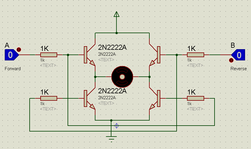
H bridge circuit proteus simulation using 555 timer #circuit #Bridge circuit motor driver simple circuits mosfet dc using transistor working diy Basic h bridge circuit diagram.
.


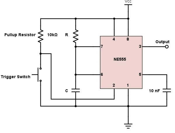
How does NE555 timer circuit work | Datasheet | Pinout | ElecCircuit.com

Fet H Bridge Circuit Diagram

H-bridge Using 555 Timer at Rs 599.00 | Lucknow | ID: 2849611077362

555 timer schematic symbol - Wiring Diagram and Schematics

555 Timer IC Working Principle, Block Diagram, Circuit, 47% OFF

Draw The Pin Diagram Of Ic 555

H Bridge Inverter Circuit Diagram